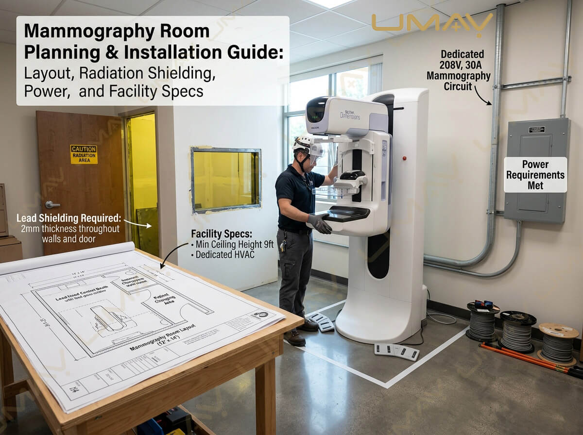
Installing a modern Full-Field Digital Mammography (FFDM) or 3D Digital Breast Tomosynthesis (DBT) system requires precise facility planning. Unlike general radiology suites, a mammography room must balance stringent radiation protection regulations, precise climate controls for delicate digital flat-panel detectors, ergonomic technologist workflows, and a warm, reassuring patient atmosphere.
Inadequate shielding design, poor power grounding, or improper HVAC calibration can lead to costly project delays, regulatory compliance failures, image noise artifacts, or premature detector degradation.
This comprehensive facility planning guide outlines room dimensions, architectural layouts, lead shielding thickness requirements, electrical specifications, and step-by-step installation workflows for hospital engineers, facility planners, and radiology directors.
2. Recommended Mammography Room Dimensions & Architectural Layout
A well-designed mammography suite should optimize workflow efficiency, accommodate technologist movement, provide absolute visual privacy for patients, and allow unhindered gantry rotation and biopsy procedures.
┌────────────────────────────────────────────────────────────────────────┐
│                        TYPICAL MAMMOGRAPHY SUITE LAYOUT                │
├────────────────────────────────────────────────────────────────────────┤
│                                                                        │
│   ┌────────────────────────┐                ┌──────────────────────┐   │
│   │ Patient Dressing Room  │                │   Operator Control   │   │
│   │ (Direct Private Door)  ├───────────────►│   Booth & Shield     │   │
│   └────────────────────────┘                │ (1.5mm Pb Lead Glass)│   │
│                                             └──────────┬───────────┘   │
│                                                        │               │
│                                                        ▼               │
│                        ┌───────────────────────────────────┐           │
│                        │                                   │           │
│                        │       Mammography Gantry          │           │
│                        │       (360° Rotation Zone)        │           │
│                        │                                   │           │
│                        └───────────────────────────────────┘           │
│                                                                        │
│   ┌──────────────────────────┐                ┌──────────────────────┐ │
│   │ Accessory Storage Cabinet│                │ Handwashing Sink /   │ │
│   │ (Paddles & Phantoms)     │                │ Clinical Supply Cart │ │
│   └──────────────────────────┘                └──────────────────────┘ │
│                                                                        │
└────────────────────────────────────────────────────────────────────────┘
Key Dimensional Parameters:
-
Minimum Room Area: 15 m² to 20 m² (approx. 160 sq. ft. to 215 sq. ft.) is recommended for standard screening and diagnostic units.
-
Biopsy-Capable Rooms: Add 3 m² to 5 m² of extra clearance if the system includes stereotactic biopsy accessories or lateral patient positioning couches.
-
Minimum Ceiling Height: 2.4 meters (approx. 8 feet) to allow full vertical travel of the motorized C-arm gantry and overhead shadow-free lighting.
-
Doorway Clearance: Minimum 1.0-meter width (approx. 36 inches) double-leaf or extra-wide door frame to permit smooth rigging, delivery, and ongoing patient access.
3. Radiation Shielding Requirements & Barrier Specifications
While mammography uses low-energy soft X-rays (typically operating between 22 kVp and 49 kVp), radiation protection standards (such as NCRP Report No. 147 and local health authority codes) mandate strict boundary shielding to protect non-occupational staff and adjacent public areas.
Lead Equivalency Standards
| Building Element | Primary / Secondary Barrier | Recommended Shielding Thickness (Lead Equivalent) |
| Control Booth Shield Wall | Primary Attenuation Barrier | 1.0 mm – 1.5 mm Pb @ 50 kVp |
| Observation Lead Glass | Direct Visual Barrier | 1.5 mm – 2.0 mm Pb @ 50 kVp |
| Gantry Perimeter Walls | Secondary Scatter Barrier | 0.8 mm – 1.0 mm Pb (or 100mm Solid Concrete) |
| Entrance Doors | Secondary Scatter Barrier | 0.8 mm – 1.0 mm Lead-lined Core |
| Floor & Ceiling | Scatter Barrier | Standard 100mm solid poured concrete (usually sufficient) |
Note: A qualified Medical Physicist must perform a formal Radiation Protection Survey and sign off on room shielding calculations prior to clinical operation.
4. Electrical Power, Supply, and Grounding Requirements
Digital mammography gantries and high-frequency X-ray generators demand stable voltage supply and clean electrical grounding to prevent line ripple, voltage drops during high-mAs exposures, and electronic detector artifacts.
                           ┌──────────────────────────────────────────┐
                           │      Dedicated Distribution Panel        │
                           └────────────────────┬─────────────────────┘
                                                │
         ┌──────────────────────────────────────┴──────────────────────────────────────┐
         ▼                                                                             ▼
┌───────────────────────────────────────┐                      ┌──────────────────────────────────────┐
│       Main Power Feed                 │                      │      Clean Earth Grounding           │
├───────────────────────────────────────┤                      ├──────────────────────────────────────┤
│ • 200 VAC – 240 VAC (±10%)            │                      │ • Resistance < 2 Ohms                │
│ • Single-phase or 3-Phase dedicated   │                      │ • Isolated equipment grounding wire  │
│ • 30A to 50A dedicated circuit breaker│                      │ • Eliminates electrical image noise  │
└───────────────────────────────────────┘                      └──────────────────────────────────────┘
Critical Electrical Parameters:
-
Nominal Line Voltage: 200 VAC to 240 VAC, 50/60 Hz (Single-phase or 3-phase depending on generator model).
-
Line Voltage Regulation: Must remain within ±10% of nominal voltage under full load conditions.
-
Dedicated Circuit Breaker: Connect the generator directly to a dedicated main distribution panel with a independent 30A to 50A circuit breaker.
-
Clean Ground Resistance: True earth ground resistance must be strictly below 2.0 Ohms. High ground impedance introduces electrical noise into sensitive digital flat-panel detector readouts.
-
Uninterruptible Power Supply (UPS): Recommended 3 kVA to 5 kVA online UPS for the operator acquisition workstation and detector backup circuit to prevent data corruption during sudden power surges or blackout events.
5. Environmental Climate Control (HVAC Requirements)
Digital flat-panel detectors—particularly Amorphous Selenium (a-Se) direct conversion detectors—are sensitive to thermal shock, high humidity, and ambient temperature shifts.
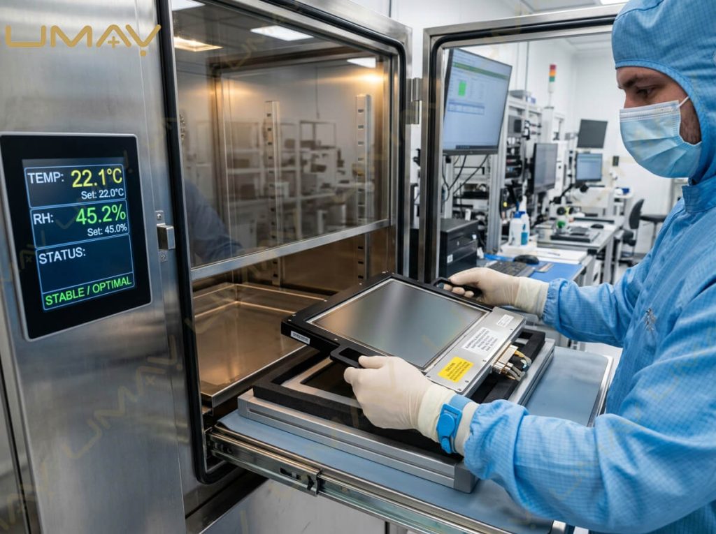
Optimal Operating Conditions:
-
Ambient Operating Temperature: Maintain between 20°C and 24°C (68°F to 75°F).
-
Temperature Drift Limit: Maximum allowable drift is < 3°C per hour to avoid thermal contraction artifacts or detector calibration drift.
-
Relative Humidity (Non-Condensing): Keep within 30% to 60% RH. Excessively dry air increases static discharge risks, whereas high humidity risks moisture condensation on cooling plates and optical filters.
-
Heat Dissipation Load: Ensure the room HVAC system can offset approximately 1.5 kW to 3.0 kW (5,000 – 10,000 BTU/hr) of heat output generated by the unit, workstations, and lighting.
6. Step-by-Step Installation & Commissioning Roadmap
Installing a mammography machine follows a strict six-stage engineering timeline:
  STAGE 1: Site Inspection & Lead Shielding Verification
     │
     ▼
  STAGE 2: Delivery, Rigging & Uncrating
     │
     ▼
  STAGE 3: Mechanical Assembly & Power Connection
     │
     ▼
  STAGE 4: Detector Calibration & Software Setup
     │
     ▼
  STAGE 5: Medical Physics Compliance Testing (MQSA/ACR)
     │
     ▼
  STAGE 6: Clinical Application Training & Go-Live
-
Site Inspection: Engineer verifies room dimensions, lead shielding continuity, electrical breaker ratings, ground resistance, and ambient HVAC performance.
-
Delivery & Rigging: Uncrate equipment in receiving bay; navigate transport dollies through pre-measured hallway access paths into the scanning room.
-
Mechanical Assembly: Mount gantry base plate, secure C-arm column, install overhead tube assembly, and wire main power lines.
-
Detector Calibration: Perform electronic offset calibration, gain mapping, bad-pixel maps, and automatic exposure control (AEC) thickness optimization tests.
-
Medical Physics Testing: Certified medical physicist executes radiation output consistency, entrance exposure limits, beam quality (HVL), and phantom image evaluations.
-
Application Training: Factory-trained specialist conducts hands-on positioning, compression, software navigation, and daily QA protocol training for site technologists.
7. Facility Installation Checklist for Hospital Engineers
-
[x] Lead Shielding Survey: Lead-lined walls and control booth glass verified by a certified medical radiation physicist.
-
[x] Floor Leveling & Load Capacity: Floor surface leveled within ±2 mm; structural slab verified to handle machine static weight (300 kg – 600 kg).
-
[x] Electrical Circuit Validation: Dedicated 200–240V power line installed with ground resistance measured at < 2.0 Ohms.
-
[x] HVAC Calibration: Room climate stabilized at 21°C (69°F) and relative humidity locked between 40% and 50%.
-
[x] Network Connectivity: Dedicated Gigabit RJ45 Ethernet drop installed near operator workstation for PACS/HIS/RIS integration.
-
[x] Emergency Cut-off Switch: Wall-mounted emergency power shut-off button installed within easy reach of operator control console.
8. Frequently Asked Questions (FAQ)
Q1: Does a digital mammography room require lead shielding?
Yes. Although mammography uses lower energy X-rays (22–49 kVp) compared to CT or general radiography, lead shielding (typically 0.8mm to 1.5mm Pb equivalent) or thick concrete density is mandatory to protect operators behind control barriers and personnel in adjacent spaces.
Q2: Why are amorphous selenium (a-Se) detectors sensitive to room temperature changes?
Amorphous selenium detector layers expand and contract in response to ambient thermal variation. Rapid temperature changes can cause gain calibration drift or structural micro-stress, making stable 24/7 HVAC climate control essential.
Q3: How much electrical power does a typical digital mammography unit consume?
Standard modern gantries consume very low standby power (~0.5 kW to 1 kW), but require up to 5 kW to 10 kW peak power for fraction-of-a-second X-ray exposures. A dedicated 30A to 50A breaker prevents voltage dips across facility sub-panels.
Q4: How long does physical installation and commissioning take?
Physical mechanical assembly usually takes 1 to 2 days. Software setup, detector calibration, medical physics safety testing, and technologist training require an additional 2 to 3 days, resulting in a typical 5-day total setup period.